Driving a stepper motor with a microcontroller
Controlling a stepper motor.
I’m sitting here after accidentally destroying another ESP32 module and 3.3v buck converter… Working with physical hardware can be a bit of a doozy coming from the world of software.
Hardware
Currently, I’ve anciently destroyed…
Parts I’ve anciently destroyed.
- x4 ESP32 Modules These get cooked with the voltage converters
- x3 Voltage Buck converters
- x1 drv8833 (didn’t realize it wasn’t a fan of 12v)
- x1 drv8825
- couple LEDs
Some of these where simply wires coming loose in the breadboard and touching things they were not supposed to. Having a multimeter on hand is a physical debugger, kinda running blind without out. (left mine in Houston)
Also included
- bread boards
- NEMA 17 motor
- Arduino Uno
- Pi Zero WH (The h means the headers are soldered to the board)
- 100 uf capacitor
- 12v Wall wart
- Barrel jack plugs
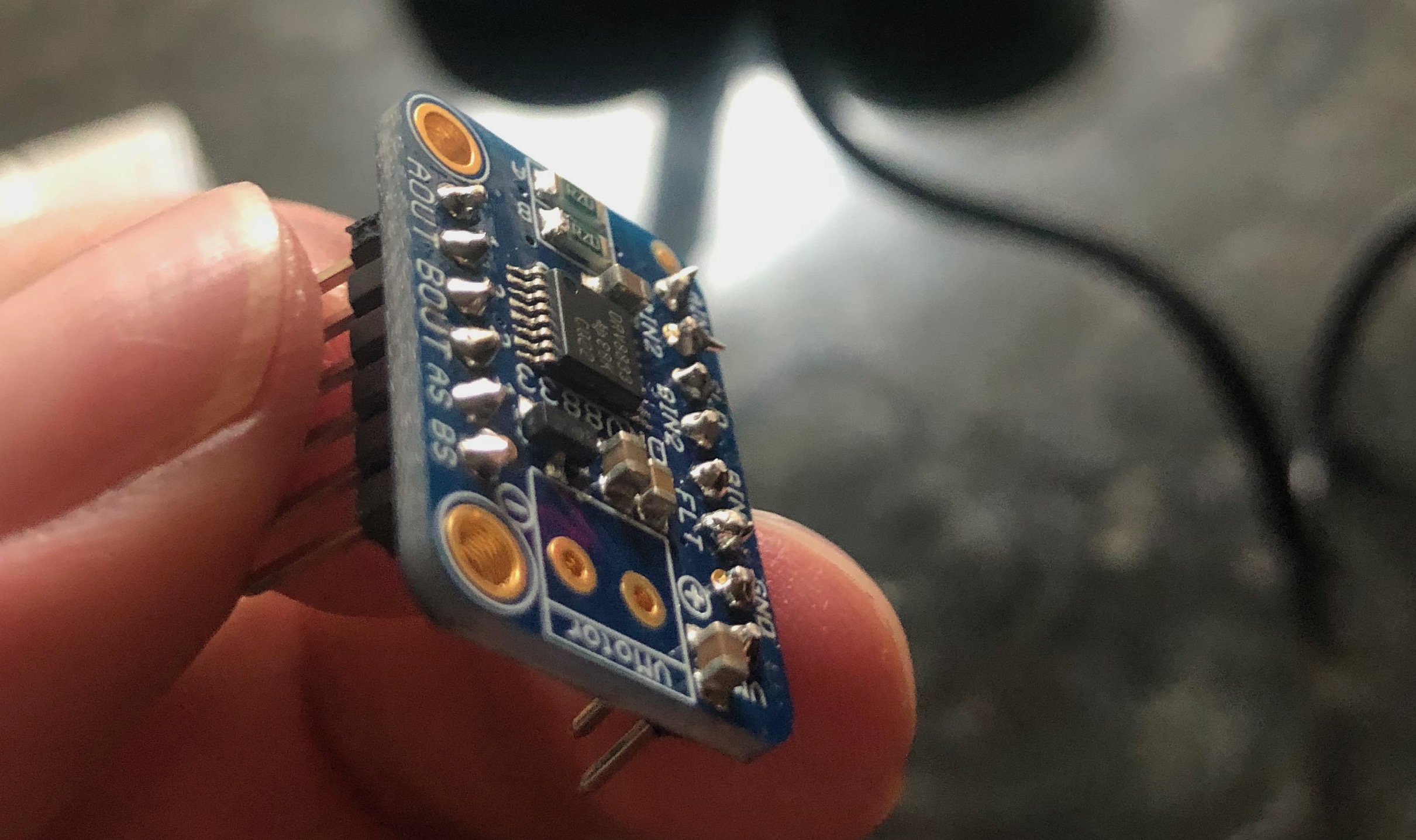
This drv8833 I had to solder the header’s to it with the help of my friend Johhny.
Hardware Background
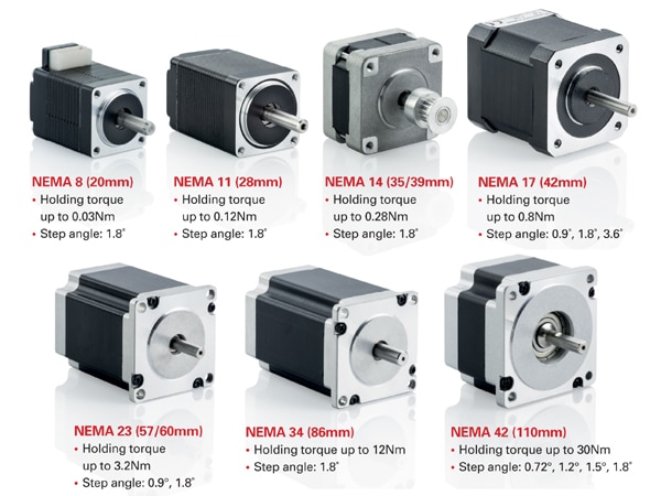
This isn’t my first time working with this kind of stuff. I built a 3D printer ages ago while printing what parts I could. The rest is ordered. The drv8833 and nema motors (National Electrical Manufacturers Association) are often used in 3D printing so I knew those where a good place to start.
Typically the number designates the faceplate size of the motor eg the four mounting points around the shaft, you can typically get the same size motor in different lengths for more or less torque. The NEMA 17 for instance has 1.7” inch faceplates. Below is a bunch of different sized images.
Power
To power the whole affair we use 2.1mm barrel jack’s on the breadboard and 12v wall-wart. This gives us the power for the drv8825/drv8833. Then we had the buck voltage converter to power the microcontroller when not plugged into USB.
Checking in your designs
Another thing I learned is taking pictures, I was able to get the motor working with the drv8833 and came back to in a few days later and was not able to reproduce so I’ve learned it’s usually a good idea to ‘check everything in’ with a few photos.
Running the stepper motor with PWM Signals
Now driving the motors using the Arduino or the ESP32 and the Arduino IDE is relatively easy. Using the Pi is a bit more involved, you need to enable kernel support for PWM and you only have two PWM outputs. With the Uno you’ll get 6, the ESP32 has 16!
This article getting the Pi hardware PWM working.
A simple working example for the Arduino IDE and ESP32 follows. This spins the motor one direction and then reverse.
/*Example sketch to control a stepper motor with A4988/DRV8825 stepper motor driver and Arduino without a library. More info: https://www.makerguides.com */

// Define stepper motor connections and steps per revolution:
#define dirPin 16
#define stepPin 17
#define stepsPerRevolution 200

void setup() {
  Serial.begin(9600);

  Serial.println("Stepper test!");

  // Declare pins as output:
  pinMode(stepPin, OUTPUT);
  pinMode(dirPin, OUTPUT);
}

void loop() {
  Serial.println("Going clockwise!");
  // Set the spinning direction clockwise:
  digitalWrite(dirPin, HIGH);

  Serial.println("One slow revolution");
  // Spin the stepper motor 1 revolution slowly:
  for (int i = 0; i < stepsPerRevolution; i++) {
    // These four lines result in 1 step:
    digitalWrite(stepPin, HIGH);
    delayMicroseconds(2000);
    digitalWrite(stepPin, LOW);
    delayMicroseconds(2000);
  }

  delay(1000);

  Serial.println("Set direction counterclockwise");
  // Set the spinning direction counterclockwise:
  digitalWrite(dirPin, LOW);

  Serial.println("One slow revolution");
  // Spin the stepper motor 1 revolution quickly:
  for (int i = 0; i < stepsPerRevolution; i++) {
    // These four lines result in 1 step:
    digitalWrite(stepPin, HIGH);
    delayMicroseconds(1000);
    digitalWrite(stepPin, LOW);
    delayMicroseconds(1000);
  }

  delay(1000);
}
It works!